The diagram settings panel enables you to change a number of diagram display settings.
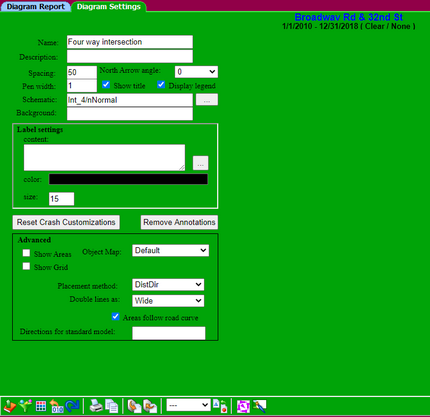
•Name - displayed at the top of the diagram.
•Description - used for tooltips in the project tree.
•Spacing - defines the distances between crashes in the same group.
•Pen width - defines how thick the crash graphic lines should be drawn.
•Show title - determines if any header information will be displayed above the diagram.
•Display legend - determines if the key will be shown at the bottom of the diagram.
•Schematic - determines which schematic will be used to locate the crash graphics and curb lines.
•Background - specify a physical file or url to display a raster image "behind" the diagram. (i.e. ortho photo).
•Label color - pick a color for the labels.
•Label content - an expression that resolves to text which will be displayed next to each crash graphic. (can also simply be a field name).
•Label size - height of the label text. (the diagram is 1000 units wide)
•Object Map - The current object map used to display the collision graphics on a diagram.
•Primitives - The current list of graphic objects used to create the object map.
•Show areas - for debugging and modifying schematics. Displays the areas where graphics will be placed, and a graduated grid for aligning them.
•Show Grid - Displays a grid on the diagram schematic.
•Reset Crashes - Returns collision graphics to their original placement.
•Remove Annotations - Removes all annotations added to the diagram.